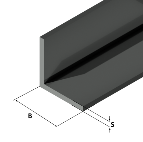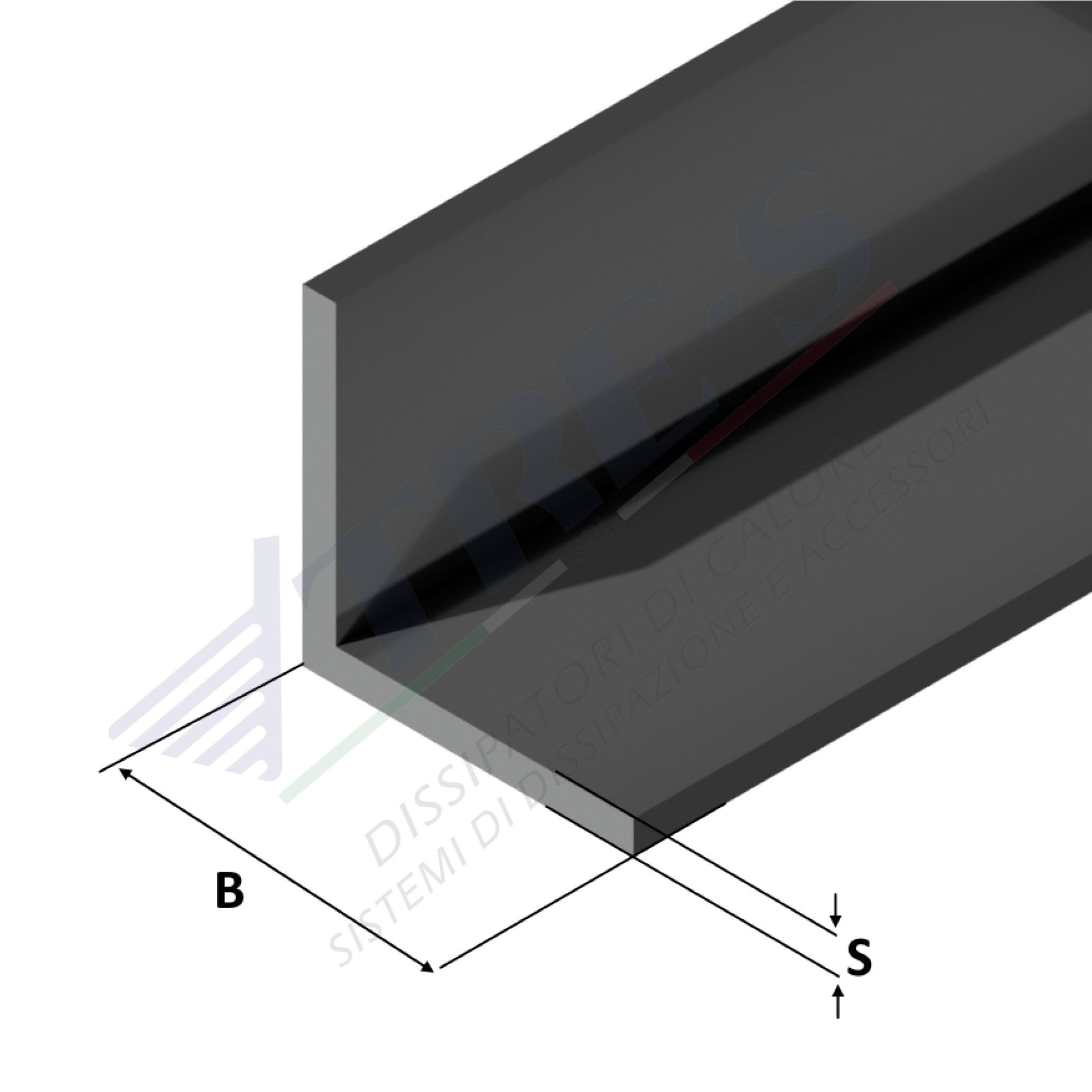

Code: Angolari lati uguali
Standard Profiles
| Lega | BxS Dimensione | Peso al metro |
|---|---|---|
| 6060 | 10x1,5 | 0,078 |
| 6060 | 15x1,5 | 0,115 |
| 6060 | 15x2 | 0,152 |
| 6060 | 20x1,5 | 0,155 |
| 6060 | 20x2 | 0,205 |
| 6060 | 20x3 | 0,3 |
| 6060 | 25x2 | 0,259 |
| 6060 | 25x3 | 0,381 |
| 6060 | 30x1,5 | 0,237 |
| 6060 | 30x2 | 0,313 |
| 6060 | 30x3 | 0,462 |
| 6060 | 30x4 | 0,604 |
| 6060 | 35x2 | 0,367 |
| 6060 | 40x2 | 0,421 |
| 6060 | 40x3 | 0,623 |
| 6060 | 40x4 | 0,82 |
| 6060 | 40x5 | 1,012 |
| 6060 | 50x2 | 0,529 |
| 6060 | 50x3 | 0,786 |
| 6060 | 50x4 | 1,037 |
| 6060 | 50x5 | 1,283 |
| 6060 | 50x6 | 1,523 |
| 6060 | 50x10 | 2,43 |
| 6060 | 60x2 | 0,637 |
| 6060 | 60x4 | 1,253 |
| 6060 | 60x6 | 1,85 |
| 6060 | 60x8 | 2,42 |
| 6060 | 60x10 | 2,97 |
| 6060 | 80x5 | 2,092 |
| 6060 | 80x8 | 3,284 |
| 6060 | 80x10 | 4,05 |
| 6060 | 100x4 | 2,116 |
| 6060 | 100x8 | 4,148 |
| 6060 | 100x10 | 5,13 |
| 6060 | 150x14 | 10,924 |
| Codice | KN MAX | I | F | H |
|---|
| Codice | KN MAX | I | F | H |
|---|
| Codice | KN MAX | I | F | H |
|---|
| Codice | KN MAX | I | F | H |
|---|
| Codice | KN MAX | I | F | H |
|---|
| Codice | KN MAX | I | F | H |
|---|
Length: 0.00 mm
Weight: 0.00 kg/m
Weight A: 0.00 kg/m
Weight B: 0.00 kg/m
Height: 0.00 mm
Within this catalog, heat sinks are organized based on their shape and dimensions expressed in millimeters. Each profile is characterized by the following parameters:
- Weight: expressed in kilograms per meter of profile length (Kg/m).
- Length: indicated in millimeters and used for calculating thermal resistance (L).
- Width: also in millimeters, considered for calculating thermal resistance (°C/W), applicable only to high-efficiency heat sinks.
- Thermal Resistance in Natural Convection: expressed in °C/W with a temperature difference of 70°C (compared to an ambient temperature of 25°C).
- Thermal Resistance in Forced Convection: also expressed in °C/W, with an air velocity of 3 m/s and a temperature difference of 50°C.
The values of thermal resistance have been determined through a thermal simulation program designed to replicate realistic conditions. In particular:
- The heat source is uniformly distributed over approximately 50% of the dissipation surface, with central positioning on the heat sink.
- To maximize natural convection heat dissipation efficiency, the heat sink is designed with vertical fins. For horizontal installations, it is advisable to consider an increase of approximately 20% in thermal resistance.
- The surface of the heat sink is not subject to additional treatments.
Regarding black anodized heat sinks in natural convection, the thermal resistance is reduced by approximately 10%.
As the length of the heat sink increases, the thermal resistance decreases following a nonlinear law. The indicated values refer to the specified lengths; for different lengths, consult the “Length Correction Factor” graph to calculate the multiplication factor to be applied to the thermal resistance, both in natural and forced convection.

