TECHNICAL AND MECHANICAL INFORMATION
- The tolerances on the nominal dimensions of the extruded profiles follow in detail the UNI 3879 (DIN 1748) standards
- All machining dimensions without tolerance indication are subject to an average degree of accuracy UNI 5307
- Threaded holes have a thread depth of at least twice their diameter
- As far as geometric tolerances are concerned, the flatness value on surfaces can be defined as 0+/-0,05 mm/m
ROUGHNESS MEASUREMENT
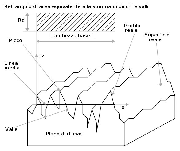
To introduce the concept of roughness measurement it is necessary to define some characteristic parameters (see figure 1):
- length of the measuring section L: this is the section of the technical profile on which roughness measurements are carried out;
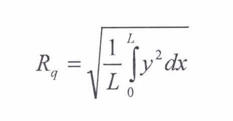
- profile mean line: is the compensation line of the real profile, parallel to the technical profile, within the limits of the length L of the measuring section. Given y the deviations of the real profile with respect to the mean line (measured orthogonally to this) and given x the distance on the mean line between the point where the profile survey begins and the point where y is measured (see fig. 1), the mean line of the profile is defined as the line for which the relationship is verified:

Figura 1 - Profilo ideale, profilo reale e profilo tecnico secondo le definizioni UNI-3963.
THE DEGREE OF FINISH OF THE MACHINED SURFACES
The measure of roughness is given by the amplitude R of the arithmetic mean value of the absolute values of the deviations y of the real profile with respect to the mean line:

R for Roughness a for arithmetic average
Roughness measurements are expressed in µm. The degree of roughness of a surface is defined as the maximum value of R among those measured at different points of the surface.

