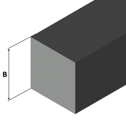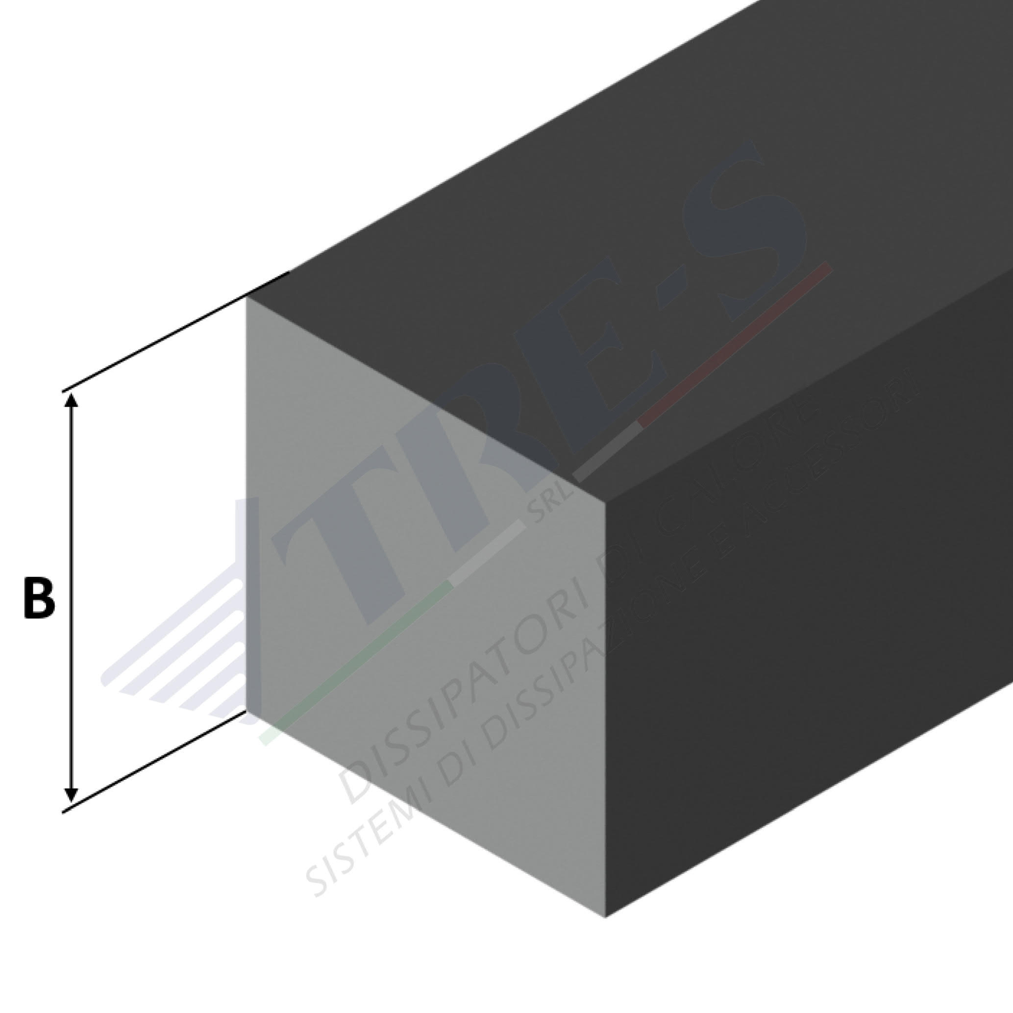

Code: Barra quadra
Standard Profiles
| Lega | BxS Dimensione | Peso al metro |
|---|---|---|
| 6060 | 6 | 0,098 |
| 6060 | 8 | 0,173 |
| 6060 | 10 | 0,27 |
| 6060 | 12 | 0,338 |
| 6082 | 15 | 0,608 |
| 6060 | 15 | 0,608 |
| 6082 | 18 | 0,875 |
| 6082 | 20 | 1,08 |
| 2011 | 20 | 1,08 |
| 6060 | 20 | 1,08 |
| 6082 | 25 | 1,69 |
| 2011 | 25 | 1,69 |
| 6082 | 30 | 2,43 |
| 2011 | 30 | 2,43 |
| 6082 | 35 | 3,307 |
| 2011 | 35 | 3,307 |
| 6082 | 40 | 4,32 |
| 2011 | 40 | 4,32 |
| 6082 | 45 | 5,468 |
| 6082 | 50 | 6,75 |
| 2011 | 50 | 6,75 |
| 6082 | 55 | 8,168 |
| 6082 | 60 | 9,72 |
| 2011 | 60 | 9,72 |
| 6082 | 65 | 11,407 |
| 6082 | 70 | 13,23 |
| 2011 | 70 | 13,23 |
| 6082 | 80 | 17,28 |
| 2011 | 80 | 17,28 |
| 6082 | 90 | 21,9 |
| 2011 | 90 | 21,9 |
| 6082 | 100 | 27 |
| 2011 | 100 | 27 |
| 6082 | 110 | 32,67 |
| 2011 | 110 | 32,67 |
| 6082 | 120 | 38,88 |
| 2011 | 120 | 38,88 |
| 6082 | 130 | 45,63 |
| 6082 | 140 | 52,92 |
| 6082 | 150 | 60,75 |
| 6082 | 160 | 69,12 |
| 6082 | 170 | 77,03 |
| 6082 | 180 | 87,48 |
| 6082 | 200 | 108 |
| Codice | KN MAX | I | F | H |
|---|
| Codice | KN MAX | I | F | H |
|---|
| Codice | KN MAX | I | F | H |
|---|
| Codice | KN MAX | I | F | H |
|---|
| Codice | KN MAX | I | F | H |
|---|
| Codice | KN MAX | I | F | H |
|---|
Length: 0.00 mm
Weight: 0.00 kg/m
Weight A: 0.00 kg/m
Weight B: 0.00 kg/m
Height: 0.00 mm
Within this catalog, heat sinks are organized based on their shape and dimensions expressed in millimeters. Each profile is characterized by the following parameters:
- Weight: expressed in kilograms per meter of profile length (Kg/m).
- Length: indicated in millimeters and used for calculating thermal resistance (L).
- Width: also in millimeters, considered for calculating thermal resistance (°C/W), applicable only to high-efficiency heat sinks.
- Thermal Resistance in Natural Convection: expressed in °C/W with a temperature difference of 70°C (compared to an ambient temperature of 25°C).
- Thermal Resistance in Forced Convection: also expressed in °C/W, with an air velocity of 3 m/s and a temperature difference of 50°C.
The values of thermal resistance have been determined through a thermal simulation program designed to replicate realistic conditions. In particular:
- The heat source is uniformly distributed over approximately 50% of the dissipation surface, with central positioning on the heat sink.
- To maximize natural convection heat dissipation efficiency, the heat sink is designed with vertical fins. For horizontal installations, it is advisable to consider an increase of approximately 20% in thermal resistance.
- The surface of the heat sink is not subject to additional treatments.
Regarding black anodized heat sinks in natural convection, the thermal resistance is reduced by approximately 10%.
As the length of the heat sink increases, the thermal resistance decreases following a nonlinear law. The indicated values refer to the specified lengths; for different lengths, consult the “Length Correction Factor” graph to calculate the multiplication factor to be applied to the thermal resistance, both in natural and forced convection.

